The vapor compressors commonly used in Mechanical Vapor Recompression (MVR) systems include Roots compressors, axial flow compressors, centrifugal fans, and centrifugal compressors.
• Roots compressors are typically used for small vapor flow rates and low-capacity evaporation systems.
• Axial flow compressors are generally applied in large-flow, high-capacity systems and are often designed as multi-stage units.
• Among industrial applications, the most widely used types are centrifugal fans and centrifugal compressors, due to their balanced performance and efficiency.
Centrifugal Fan
A centrifugal fan is suitable for applications with a low compression ratio, typically with a pressure ratio (π) of up to 1.25.
Similar to centrifugal compressors, gas enters the impeller axially and is discharged in the radial direction under centrifugal force.
The impeller and casing are typically fabricated using welded plate structures, with reinforcing ribs added when necessary to ensure mechanical strength. In most cases, a gearbox is not required, as the drive system can directly achieve the necessary impeller speed.
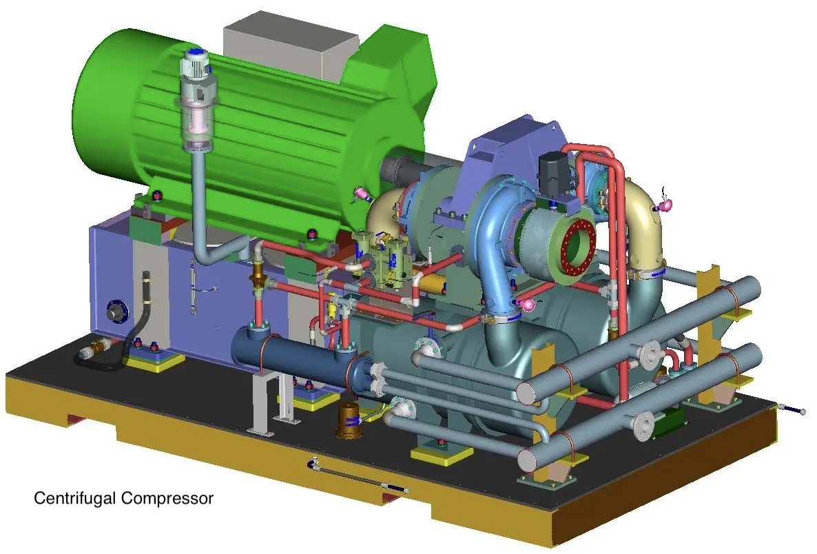
Single-Stage Centrifugal Compressor
A single-stage centrifugal compressor is characterized by a compact mechanical layout, typically consisting of an overhung impeller, compressor casing, and gearbox arranged in an integrated configuration.
Key components such as the motor, gearbox, and compressor are usually mounted on a common base frame. The compressor casing may be either cast or welded, depending on design requirements.
Due to the high tip speed of the impeller (often exceeding 400 m/s), the impeller is subjected to significant mechanical stress. Therefore, high-strength materials such as chromium-nickel steel or titanium alloys are commonly used to ensure structural reliability.
Multi-Stage Centrifugal Compressor
Multi-stage centrifugal compressors are used in applications requiring high vapor flow rates and significant temperature lift of saturated steam.
The compressor consists of multiple impeller stages arranged on a single shaft. After leaving the first stage, the vapor passes through an interstage diffuser and return channel before entering the next impeller stage.
The rotor shaft is supported by bearings housed within the casing and is driven through a gearbox system.
To improve efficiency and control temperature rise, liquid injection (such as water injection) may be applied in interstage sections to reduce gas temperature and stabilize operation.
For applications requiring a pressure ratio greater than π ≈ 10, multiple compressor units may also be arranged in series.
Depending on the drive configuration, compressors with multiple impellers driven through a central gearbox may also be referred to as two-, three-, or four-impeller systems.
Contact Us
Reach out to an optimized proposal